Unity 5 was released in March 2015 and brought many new features, but perhaps the most important feature is physically based rendering. This new lighting model simulates the natural interactions of light rays and real-world materials. The math behind physically based rendering (or PBR for short) is indeed complicated, but Unity makes it easy to create dynamic materials with beautiful contrast and detail. While this post will not detail how to author texture maps in a program like Photoshop or Allegorithmic Substance Designer, you’ll learn the basics of PBR and how it’s implemented in the Unity game engine.
Contents
The Benefits of Physically Based Rendering
Beyond the basic definition, the scope of PBR includes new types of texture maps, new shaders, and perhaps most importantly, a new way of working. In other words, it’s not a standard or simply a new piece of technology. Rather, it’s a shift in the entire art pipeline across the gaming industry. The principles of PBR were pioneered by Disney and Pixar for use in offline rendering and animated films, but advances in hardware and software have made PBR possible in real-time rendering for games. Thus far, various forms of PBR have been implemented in both the Unity and Unreal game engines, as well as in major art tools like Autodesk Maya and Allegorithmic Substance Designer.
PBR demands big changes to traditional art pipelines, but the benefits are usually well worth the effort.
Most importantly, PBR delivers more consistent and predictable results. For the last few decades, 3D game artists were only able to create textures that look good under specific lighting conditions. However, as soon as the lighting changed or the environmental context shifted, an asset would need to be tweaked to look good again.
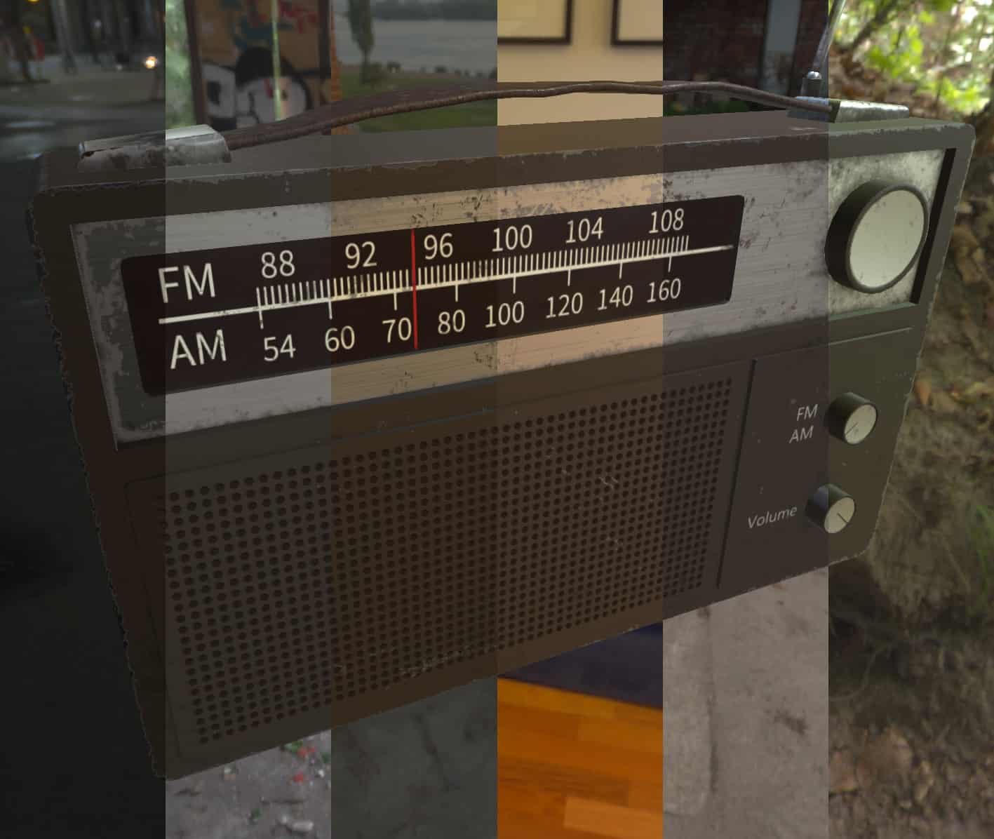
With PBR, assets will look the way you’d expect when there are changes in lighting or in the environment. Almost all PBR renderers use some form of image-based lighting, which allows assets to pick up colors from the surrounding environment. See the screenshot below to see how the same asset looks how you might expect even when it’s in different environments.
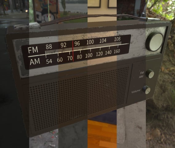
This radio asset uses one set of textures, but when placed under different lighting conditions, the various materials like leather, plastic, and metal, all behave the way you would expect.
Another huge benefit of PBR is the ability to create realistic results quickly. While physically based rendering is great for creating stylized assets, it really shines when the goal is realism. This is because PBR uses scientifically calibrated color for known real-world materials, which reduces guess-work and trial-and-error.
As a technical note, I should point out that there are two PBR workflows, typically known as Metallic-Roughness and Specular-Glossiness. One isn’t necessarily better than the other, but because the Standard shader in Unity uses a workflow that’s very similar to Metal/Rough by default, this post will only focus on the Metal/Rough workflow.
The Unity 5 Standard Shader
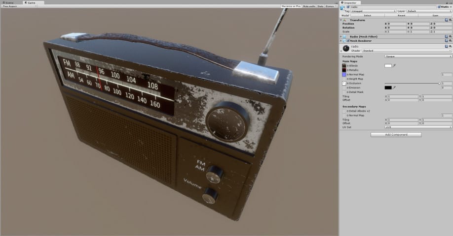
In Unity, any new 3D object you create will have a Material component attached. By default, the Material will use the Standard shader. The screenshot below is from Unity and features an asset that uses the Standard shader.
A shader is a small computer program that performs the necessary calculations to describe the appearance of a surface. Typically, a shader takes input data to modify its behavior. Sometimes these inputs are numbers, but often the input data is in the form of 2D texture maps. In Unity and most other 3D applications, a Material is the combination of a shader and texture maps. In the case of Unity’s default Standard shader (and most other PBR shaders), there are several texture map slots (also sometimes called “channels”). The three most important ones are:
- Albedo
- Metallic
- Normal
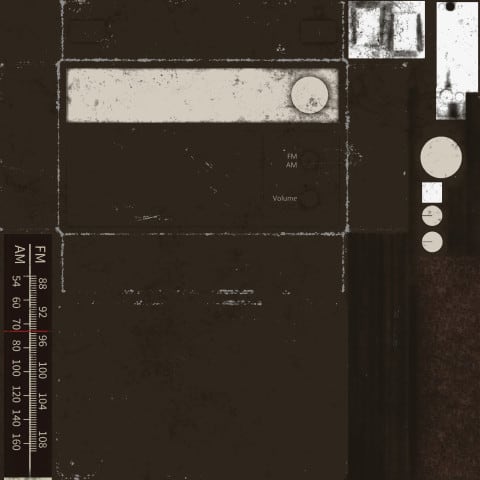
Albedo
This texture map describes color as viewed in perfectly diffused lighting conditions, with no faked shadows of any kind. PBR is able to quickly produce believable results because the albedo map uses pre-calibrated sRGB values for known materials. When creating a material like aluminium, gold, or coal, you can simply refer to a PBR chart and get the scientifically accurate value. For example, here is Unity’s official calibration chart.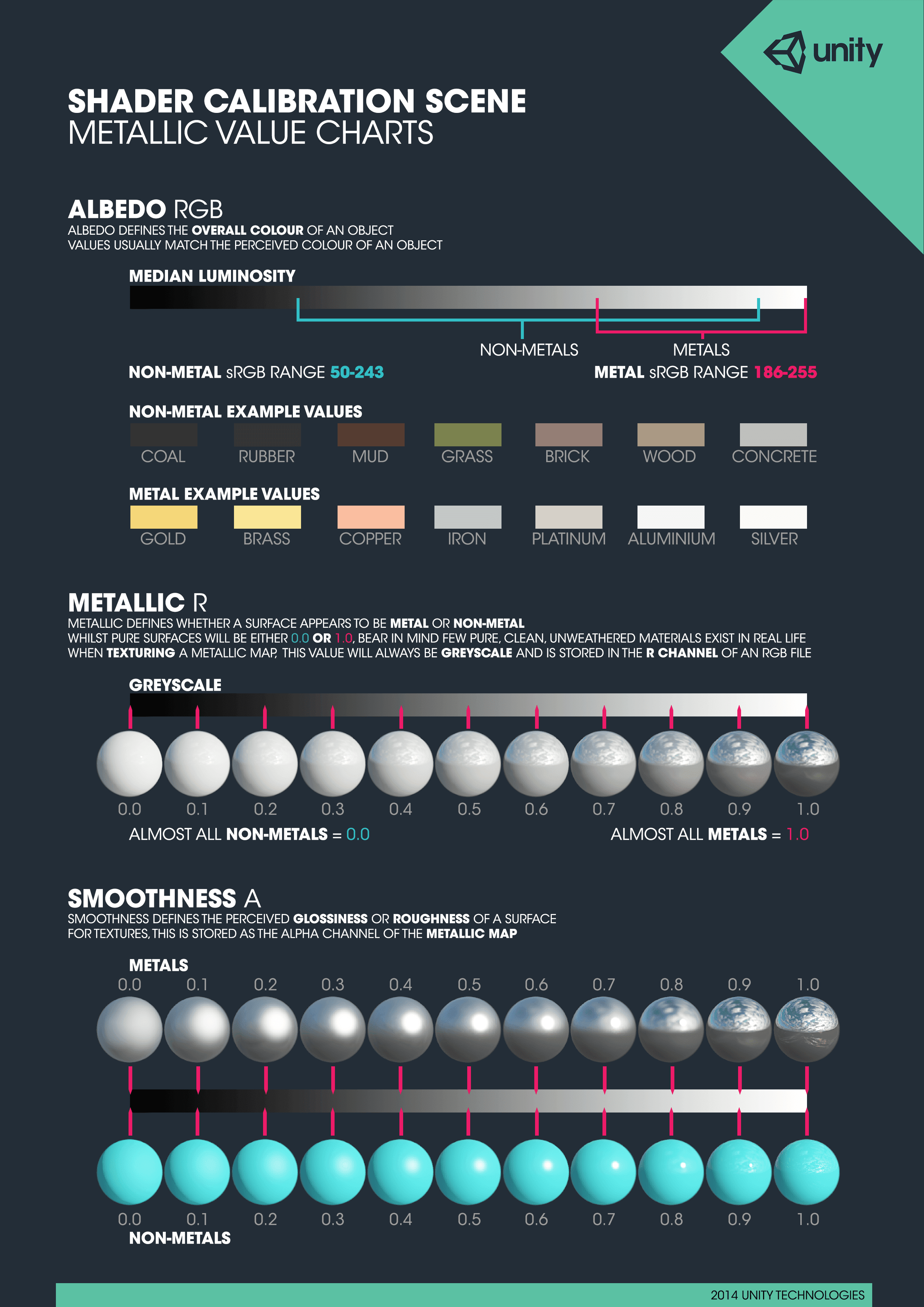
Many of the measured sRGB values may seem surprisingly bright. For example, it might seem like coal should be almost completely black. However, almost nothing is perfectly black or white in the real world, but black coal or white snow has this appearance because of the lighting conditions under which they are typically viewed. In addition, color tends to be perceived on a relative scale as our eyes adjust to lighting conditions.
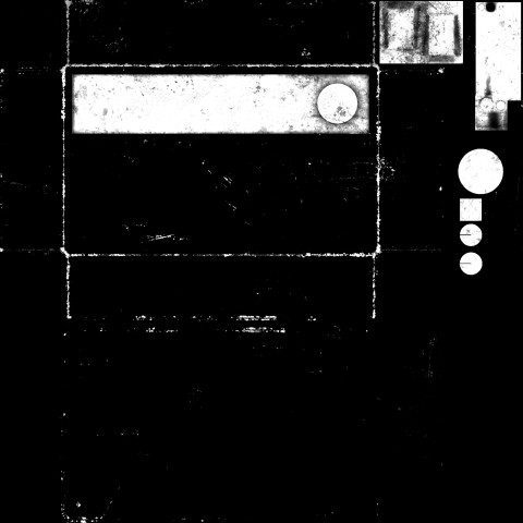
Metallic
The metallic map in Unity is actually a combination of two maps into one to save texture memory. This is possible because both are grayscale maps and only occupy one channel of the RGBA color space. In Unity, the R channel is for the metallic map and the A (alpha) channel is for smoothness. For this reason, I’ll explain the metallic map and the smoothness map separately, but just know that they are combined into a single map called “metallic” in the Unity Standard shader.
PBR materials that use a metallic map, as is the case with Unity’s Standard shader, fall into two categories: metal or non-metal. Sometimes, a non-metal is also called a dielectric, meaning it’s a poor conductor of electricity. The reason for this split is because a PBR material needs to describe how light should be reflected on each surface. Reflections on metal surfaces tend to be colored, while reflections on non-metal surfaces are more neutral. Think about the difference between the reflections on a smooth chrome car bumper and a smooth piece of plastic, and you’ll get the idea. The Unity PBR calibration chart above shows a good example of this at the far right side of the Smoothness scale.
A metallic map simply describes which parts of a material are metal and which parts are not metal. White pixels are metal, black pixels are non-metal, and usually you should avoid anything between. The only time you might have a very light gray value is if a non-metal (like dirt or dust) is partially occluding a metal (like aluminium) underneath. Here’s a fun question to think about: If a material is made out of aluminum that has been painted over with latex paint, should the metallic map appear mostly black, or mostly white? The answer is black, because the latex paint is the outermost layer and paint is a dielectric. However, if some of the paint is chipping away, then the chipped-away bits revealing the raw metal underneath should be colored white in the metallic map.
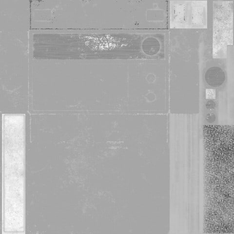
Smoothness
The smoothness map describes how smooth or rough a surface appears. Similar to the metallic map, this is also a grayscale map. White pixels in the smoothness map are 100% mirror-like and very shiny, while black pixels won’t pick up any reflections. This map does not use any measured values, and in fact, it’s a great opportunity for creativity and environmental story telling. For example, think about the difference between a brushed aluminum and a shiny mirror-like aluminum (check out Unity’s PBR calibration chart for examples). A material might start out shiny and new, but the smoothness map can communicate a lot by describing how the surface has weathered over time.
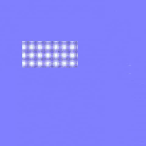
Normal
Normal maps are a fairly advanced topic that I plan to cover in a future blog post, but in general, the normal map describes the direction that light should bounce off a surface. This is a powerful tool for manipulating materials, because it allows for additional textural detail, bumps, and indentations across a surface. It’s also a great way to increase rendering performance. For example, if all the holes on the speaker of the radio asset were modeled geometry, it would be too detailed for most real-time rendering scenarios. Instead, these tiny holes are “modeled” in the normal map. The surface is actually completely smooth on the 3D model, but the normal map includes additional detail about how light should bounce on the surface, creating the illusion of small circular shadows that look like tiny speaker holes.
More PBR Tips
This post just covered the basics of Physically Based Rendering and its implementation in Unity. I didn’t cover how to actually make these texture maps, but I plan to in a future blog post. However, if you’d like to learn about how the radio asset was made, you can read part one and part two describing how it was modeled and textured.



… and here I was using only an albedo and normal with little thought… I assumed normal map was a synonym for bump map; I’ve still got a lot to learn! Thank you so much for this! I learned something new and have a whole new rabbit hole of Wikipedia articles to research 🙂
Its GREAT tutorial! VERY useful and helpful!
Great & comprehensive information. Thank you very much.
Great tutorial
– but if I understand things correctly the roughness map is the smoothness in Unity but is layered under the metallic “channel” but as the alpha channel – and the metallic map is layered as the R(ed) channel?
It is a so helpful post. Thanks a lot.
Physically based rendering has transformed computer graphics lighting by more accurately simulating materials and lights, allowing digital artists to focus on cinematography rather than the intricacies of rendering. First published in 2004
Thank you for the great tutorial!
May I know how do you create the texture for metallic?
Thank you!
Very well explained! Thanks so much.